Showing posts with label Firewall. Show all posts

Filtering logs in monitoring tab of Palo Alto

One of the best feature I loved in NGFW palo alto network is its search functionality .By default all log files are generated and stored locally on the firewall .

Filtering of traffic in monitor tab of paloalto helps us to find many things including
1.whether a traffic is getting allowed or denied
2.To filter traffic based on host, zone, port, action etc
3.To filter traffic between a specified time
4.Filter traffic from a particular user
5.Filter traffic to or from a specific IP /Network /Zone

In some cases we should have successfully created the policy in PaloAlto but we may forget to add the needed port in  that rule.When a user is complaining that he is not able to access a particular service in a  particular server we can easily figure out whats going on by reviewing the logs in monitoring tab of PaloAlto.

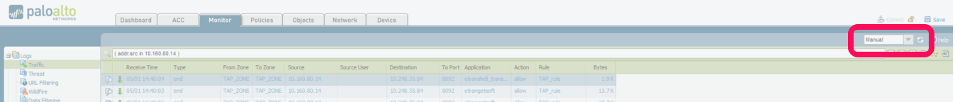
Login to PaloAlto and Goto Monitor > Traffic(left tab).There you can see the traffic flow .To change the automatic refresh interval, select an interval from the drop-down (1 min, 30 seconds, 10 seconds,or Manual).

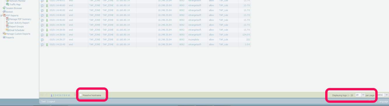
To change the number of log entries per page, select the number of rows from the Rows drop-down

Select the Resolve Hostname check box to begin resolving external IP addresses to domain names.


To filter traffic from source 

1.Click on any IP in the source field
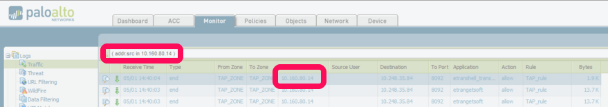
2.It will automatically add addr.src in x.x.x.x in the filter bar. eg (addr.src in 10.160.80.14) 
3.Press ENTER.
4.It will show all the traffic generating from 10.160.80.14
5.Edit IP as per your need.


Some other examples

Destination Filter: (addr.dst in 192.168.2.6) - shows all traffic with a destination address of a host that matches 192.168.2.6
Filter a source network : ( addr.src in 192.168.10.0/24 ) - shows all traffic from network  192.168.10.0/24
Filter a destination network : (addr.dst in 192.168.10.0/24)  - shows all traffic to network  192.168.10.0/24

Filter using Source and Destination

(addr.src in 1.1.1.1) AND (addr.dst in 2.2.2.2) - shows all traffic coming from a host with an IP address of 1.1.1.1 and going to a host destination address of 2.2.2.2

Filter for source OR destination

(addr in 1.1.1.1) - Shows all traffic with a source OR destination address of a host that matches 1.1.1.1

Zone Traffic Filter Examples 

FROM ZONE TRUST

(zone.src eq TRUST) - shows all traffic coming from the TRUST zone

TO ZONE UNTRUST

(zone.dst eq UNTRUST) - shows all traffic going out the UNTRUST zone

(zone.src eq TRUST) and (zone.dst eq UNTRUST) - shows all traffic traveling from the TRUST zone and going out the through UNTRUST

PORT Traffic Filter Examples

FROM PORT 22

(port.src eq 22)- shows all traffic traveling from source port 22

TO PORT 80

(port.dst eq 80)- shows all traffic traveling to destination port 80

Allowed/Denied Traffic Filter Examples 

 ALL TRAFFIC THAT HAS BEEN ALLOWED BY THE FIREWALL RULES

(action eq allow) 
OR
(action neq deny)

Example: (action eq allow)- Shows all traffic allowed by the firewall rules.

NOTE: Placing the letter 'n' in front of 'eq' means 'not equal to,' so anything not equal to 'deny' is displayed, which is any allowed traffic.

ALL TRAFFIC DENIED BY THE FIREWALL RULES

(action eq deny)
OR
(action neq allow)

Example: (action eq deny) - Shows all traffic denied by the firewall rules.

NOTE: Placing the letter 'n' in front of 'eq' means 'not equal to,' so anything not equal to 'allow' is displayed, which is any denied traffic.

TRAFFIC from a particular user

(user.src eq 'Sysnet\Shabeer') - Shows traffic from that particular user [Sysnet is domain and shabeer is username]

Combining Traffic Filter Examples

Show denied traffic from SOURCE 123.24.10.23 

(addr.src in 123.24.10.23 ) and (action eq deny)

Allowed TRAFFIC FROM SOURCE 11.10.21.21 to DESTINATION ADDRESS 20.20.20.56 in PORT 80

(addr.src in 11.10.21.21) and (addr.dst in 20.20.20.56) and (port.dst eq 80) and (action eq allow)

ALL TRAFFIC FROM ZONE DEVELOPMENT AND SOURCE NETWORK 11.10.21.0/24 TO DESTINATION ADDRESS 20.20.20.21 IN THE SECURITY ZONE:

(zone.src eq DEVELOPMENT) and (addr.src in 11.10.21.0/24) and (addr.dst in 20.20.20.21) and (zone.dst eq SECURITY) 

NOTE : You don't need to remember any of the filters mentioned above.Its very simple to create even complex filters .You can simply click the needed criteria on the logs and it will automatically add to the filtering.You just need to edit the particular zone/IP address/Port number or Action

For example
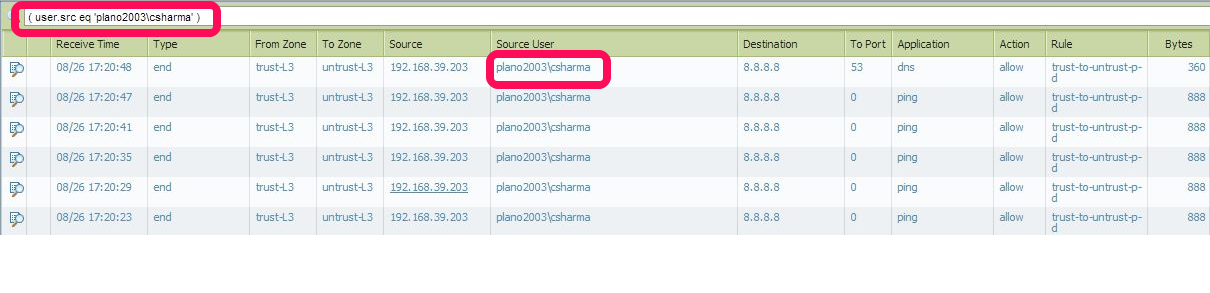
Below screenshot shows traffic from user plano2003\csharma. If you want to search custom user all you need to do is to
1. Click on any user below "Source user"  here it is (user.src eq 'plano2003\csharma')
2.Then it will add(user.src eq 'plano2003\csharma') to the filter bar. edit it with your custom username
Conclusion
1.To create a filter go to Monitor > Traffic
2. Just CLICK on the custom field you need to make a filter ie click on any field under From Zone / To Zone / Source / Source user / Destination / To port / Application / Action .In the above example we create filter using source user
3.Edit the IP/ZONE/PORT/ACTION as per your need
4..Press ENTER and it will show the custom traffic you need to see.
Read More...

Palo Alto Network NGFW Architecture

Next Generation firewalls does much more duties than a legacy firewalls which  lncludes firewall policy, URL Filtering, IPS, Antivirus,Anti-spyware,file blocking,wildfire etc. .This results in  consuming a lot of Firewall hardware resources like CPU consumption, or memory utilization.

To overcome such situations Palo Alto Networks next-generation firewalls are build based on a unique Single Pass Parallel Processing (SP3) Architecture .This combines two components:
  • Single Pass software
  • Parallel Processing hardware


The SP3 architecture is a unique approach to hardware and software integration that simplifies management, streamlines processing and maximizes performance

The combination of Single Pass software and Parallel Processing hardware is completely unique in network security, and enables Palo Alto Networks next-generation firewalls to restore visibility and control to enterprise networks at very high levels of performance.


The Control Plane has its own dual core processor, RAM, and hard drive. This processor is responsible for tasks such as management Ul, configuration, logging, and reporting.

The Data Plane contains three types of processors :
  • Signature Match Processor: Performs vulnerability and virus detection
  • Security Processors: Multi-core processors, which handle security tasks such as SSL decryption
  • Network Processor: Responsible for routing, NAT, and network layer communication

How packet flow in Palo Alto Firewall?

Basic:

Initial Packet Processing —-> Security Pre-Policy —-> Application —-> Security Policy —-> Post Policy Processing

Advance:

Read More...

How to view the details of Threats / attacks in PaloAlto Firewall

In PaloAlto, by default all log files are generated and stored locally on the firewall 

To view the details of Threats Goto Monitor tab > Threats

Each entry includes the date and time, a threat name or URL, the source and destination zones, addresses, and ports, the application name,and the alarm action (allow or block) and severity.

Threat tab Displays an entry when traffic matches a Security Profile (Antivirus, Anti-Spyware,Vulnerability, URL Filtering, File Blocking, Data Filtering, or DoS Protection) that is attached to a security rule on the firewall. 

The Type column indicates the type of threat, such as “virus” or “spyware.” The Name column is the threat description or URL

To view all the traffic from attackers IP .Go to Monitor tab > Traffic and in filter bar give the attackers IP as source address in the format (addr.src in 202.103.52.147) and press ENTER. It will show all the traffic from that IP.


Read More...

General settings in PaloAlto Firewall

Setup Hostname and Login Banner.


1. Select Device > Setup > Management and edit the General Settings.
2. Enter a Hostname for the firewall and enter your network Domain name. The domain name is just a label; it will not be used to join the domain.
3. Enter Login Banner text that informs users who are attempting to log in that they are that they must have authorization to access the firewall management functions.

Setup DNS


Select Device > Setup > Services.
1. On the Services tab, Enter Primary and secondary DNS
2. For Update Server, enter the IP address or host name of the server from which to download updates from Palo Alto Networks. The current value is updates.paloaltonetworks.com. Do not change the Update Server unless instructed by Technical Support.

NOTE : You must manually configure at least one DNS server on the firewall or it will not be able to resolve hostnames; it will not use DNS server settings from another source, such as an ISP.

Setup a secure password for the admin account.


1. Select Device > Administrators.
2. Select the admin role.
3. Enter the current default password and the new password.
4. Click OK to save your settings.

 Service Route Configuration


By default, the firewall uses management interface to communicate to various servers including DNS, Email, Palo Alto Updates, User-ID agent, Syslog, Panorama  etc. Service routes are used so that the communication between the firewall and servers go through the dataplane.

 To change this Go to Device > Setup > Services > Service Route Configuration and configure the appropriate service routes

As always dont forget to COMMIT the changes

Reboot or Shutdown PAN device


Go to Device > Setup >Operations>Device Operations
From here you can reboot or shutdown PAN device

Read More...

Initial Configuration of PaloAlto Network Firewall

By default, the firewall has an IP address of 192.168.1.1

First step we need to do is to assign a IP in the range 192.168.1.X to our machine which is going to connect to PAN device


Once the IP is configured ,Connect our machine to the PAN management Interface using a RJ-45 cable

From a browser, go to https://192.168.1.1 

Add security exception


Once you get the login page ,Give username : admin ,Password : admin


Once credentials are given you will be login to the PAN device


We will be notified that we should change our credentials, which we need do in a later step:
Once you are able to login,You can get the default page like below

This page is customized  using widgets .We can drag or drop widgets as per our desire

Setup Management IP address

1. Select Device Tab> Setup > Management and then edit the Management Interface Settings.

2. Enter the IP Address, Netmask,

To prevent unauthorized access to the managementinterface, it is a best practice to Add the Permitted IP Addresses from which an administrator can access the
MGT interface. [Optional]
3. Select which management services to allow on the interface.Make sure Telnet and HTTP are NOT selected because these services use plain text and are not as secure as the other services and could compromise administrator
credentials.

5. Click OK

6. To complete this we need to make sure we COMMIT the changes.For this we need to click the commit button at the right top of the screen

Once you click on that you will get a pop-up 
.
Click OK for that
 

You may be noticing that while changing the management it wont be getting to 100%.This is because the old IP 192.168.1.1 is changed to the new

You can type the new IP https://x.x.x.x.x in the new browser and you can access the web console again
Read More...

What is the difference between IDS , IPS and Firewall ?

A firewall is simply just a set of filters/rules that are matched against traffic. It can only detect malicious traffic trying to enter a computer system but can not detect anything which has entered the system. A firewall is considered a first line of defense in protecting private information. For greater security IDS and IPS systems should be used along with the firewall.

An IDS (Intrusion Detection System) is passive meaning it basically sits watching packets go through the network. It has a set of rules which it matches the packets against and sets off an alarm if it detects anything suspicious, usually the administrator is alerted. An IDS can detect several types of malicious traffic that would slip by a typical firewall, including network attacks against services, data-driven attacks on applications, host-based attacks like unauthorized logins, and malware like viruses, Trojan horses, and worms. Most IDS products use several methods to detect threats, usually signature-based detection, anomaly-based detection, and stateful protocol analysis.

An IPS (Intrusion Prevention System) has all the features of a good IDS, but can also stop malicious traffic from invading the enterprise. Unlike an IDS, an IPS sits inline with traffic flows on a network, actively shutting down attempted attacks as they’re sent over the wire. It can stop the attack by terminating the network connection or user session originating the attack, by blocking access to the target from the user account, IP address, or other attribute associated with that attacker, or by blocking all access to the targeted host, service, or application.

Read More...

Cisco ASA - Remote Management (via TELNET)

Cisco ASA - Remote Management (via TELNET)

1. Log on to the firewall > Go to enable mode > Go to configure terminal mode.

CiscoASA> enable
Password: ********
CiscoASA# configure terminal
CiscoASA(config)#

2. Syntax to configure TELNET is "telnet {ip address} {subnet mask} {interface that its connected to}.

The following will just allow one host (192.168.1.100).

CiscoASA(config)#telnet 192.168.1.100 255.255.255.255 inside

The following will just allow a whole network 192.168.1.1 to 254

CiscoASA(config)#telnet 192.168.1.0 255.255.255.0 inside

3. To set the password you use the "passwd" command (yes that's spelled correctly).

CiscoASA(config)# passwd PASSWORD123

4. By default the telnet session times out after 5 mins, To change it use below command

CiscoASA(config)# telnet timeout45 (set timeout to 45 min)

5. Don't forget to save the configuration

CiscoASA# write mem

Telnet - Via ASDM

1. Connect via ASDM > Navigate to Configuration > Device Management > Management Access > ASDM/HTTPS/Telnet/SSH > Add > Select Telnet > Supply the IP and subnet > OK. (Note you can set the timeout on this page also).


NOTE:  Be aware, all ASA devices running an operating system of 8.4(2) or newer, you can NO LONGER LOG IN WITH A USERNAME OF PIX, and the telnet password, you HAVE TO define a username and password, then enable AAA Authentication for SSH.
Read More...

Cisco ASA Basic Notes – Configuration Modes

A Cisco ASA security appliance has four main administrative access modes:

Monitor Mode:
Displays the monitor> prompt. This mode enables to update the image over the network or to perform password recovery. While in the monitor mode, you can enter commands to specify the location of a TFTP server and the location of the software image or password recovery binary image file to download. You access this mode by pressing the “Break” or “ESC” keys immediately after powering up the appliance.

Unprivileged Mode:
Displays the > prompt. This prompt will be available when you first access the appliance.In new Cisco ASA 5500 Series, the prompt is ciscoasa>
This mode provides restricted view of the security appliance. On this menu, you cannot configure anything from this mode. To get started with configuration, the first command you need to know is the enable command. Type enable and hit Enter. The initial password is empty, so hit Enter again to move on the next access mode (Privileged Mode).

ciscoasa> enable <–this is to enter to  Unprivileged Mode
password:               <– Enter a password here (initially its blank)
ciscoasa#                <– Privileged Mode

Privileged Mode:
Displays the # prompt. Enables you to change the current settings. Any unprivileged command also works in this mode. From this mode you can see the current configuration by using show running-config. Still, you cannot configure anything yet until you go to Configuration Mode.You access the Configuration Mode using the “configure terminal” command from the Privileged Mode.

Configuration Mode:
This mode displays the (config)# prompt. Enables you to change all system configuration settings. Use exit from each mode to return to the previous mode.

ciscoasa> enable <– Unprivileged Mode
password:            <– Enter a password here (initially its blank)
ciscoasa# configure terminal <– Privileged Mode
ciscoasa(config)# <– Configuration Mode
ciscoasa(config)# exit
ciscoasa# exit   <– Back to Privileged Mode
ciscoasa>  <– Back to Unprivileged Mode

The (config)# mode is usually called Global Configuration Mode. Some configuration commands from this mode enter a command-specific mode and the prompt changes accordingly. For example the interface command enters interface configuration mode as shown below:

ciscoasa(config)# interface GigabitEthernet 0/1
ciscoasa(config-if)#  <– Configure Interface specific parameters
Read More...

Connect Fortinet Firewall to Internet in NAT/Route mode

To Connect and configure a new FortiGate unit to securely connect a private network to the Internet.The FortiGate unit should also protect the private network from Internet threats but still allow anyone on the private network to freely connect to the Internet.


Steps to Configure


1 Connect the FortiGate wan1 interface to your ISP-supplied equipment.

2 Connect the internal network to the FortiGate internal interface.
3 Power on the ISP's equipment, the FortiGate unit, and the PCs on the Internal network.
4 From a PC on the Internal network, connect to the FortiGate web-based manager.
You can configure the PC to get its IP address using DHCP and then browse to
https://192.168.1.99.
You could also give the PC a static IP address on the 192.168.1.0/255.255.255.0 subnet.
5 Login using admin and no password.
6 On the sidebar menu, go to System > Network > Interface and select wan1.
7 Select Edit and change the following settings:


8 Select OK.
9 Select internal, then select Edit.
10 Change the following settings:


11 Select OK.
12 Go to Router > Static > Static Route and select Create New. 
13 Add the following default route:.

14 Select OK.
15 Go to Policy > Policy > Policy and select Create New.
16 Add the following security policy that allows users on the private network to access the Internet.

17 Select Enable NAT and Use Destination Interface Address.
18 Select OK.

To Confirm

Open a web browser and browse to www.fortinet.com.
Go to Policy > Policy > Policy. Right-click on any of the column headings and select Column
Settings and add the Count column. This information shows the packet counts for the security
policy you added to verify that it is processing traffic.

Your FortiGate model may already have the Count feature set by default.

Go to Policy > Monitor > Policy Monitor to view the sessions being processed by the FortiGate unit.

A graph illustrating active sessions for each policy is displayed. Since there is only one policy, the
graph contains only one entry. You can select the bar graph for policy 1 to view the top sessions by
source address, destination address, or destination port.
Read More...